
Creating a DIY cable tester with Arduino can be a practical way to verify various cable connections without spending a lot of money. By designing a simple yet effective circuit, you can identify broken or miswired cables quickly and accurately. While the concept sounds straightforward, building a reliable tester involves understanding circuit components and proper wiring techniques. If you’re interested in developing a customizable tool tailored to your needs, exploring this project could be worth your time.
Key Takeaways
- Design a circuit with resistors, optocouplers, and transistors to safely connect Arduino to various cable types.
- Select durable components rated for appropriate wattage and voltage to ensure reliability.
- Use Arduino digital pins to send/receive signals, with LEDs or displays for instant test feedback.
- Implement a stable 5V power supply, ensuring sufficient current and proper power management for all components.
- Incorporate grounding, shielding, and signal isolation to enhance safety, reduce noise, and improve test accuracy.

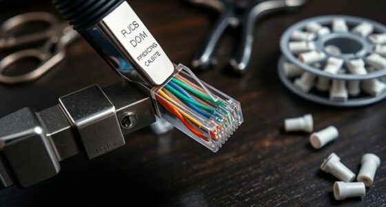
If you’ve ever struggled to identify faulty or mismatched cables, building a DIY cable tester with an Arduino offers a simple and effective solution. The core of this project lies in designing a reliable circuit that can accurately test cable continuity and pinouts. Your first step involves understanding the circuit design, which serves as the blueprint for connecting the Arduino to the cables. A well-planned circuit ensures that signals are correctly routed, and potential faults are easily detectable. You’ll want to incorporate components like resistors, transistors, and optocouplers to isolate signals and protect your Arduino from voltage spikes. The circuit must be robust enough to handle different cable types, including twisted pair, coaxial, or multi-conductor cables. Proper circuit design is essential for ensuring reliable testing results and safety.
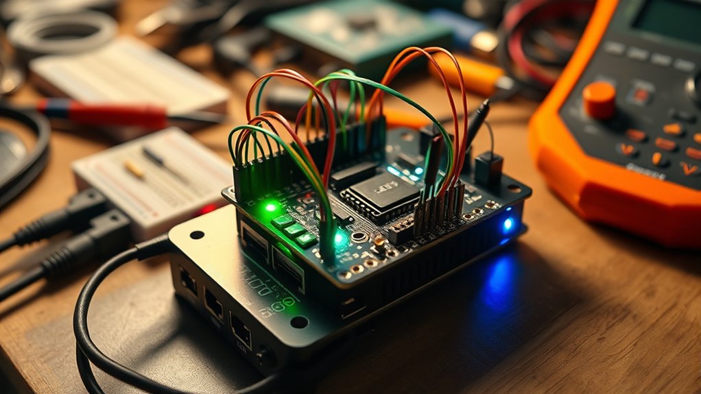
Build a reliable Arduino cable tester to identify faults and ensure proper connections.
Component selection plays a critical role in ensuring your tester functions properly and remains durable over time. You should choose resistors with appropriate wattage and resistance values to prevent overheating and ensure accurate readings. Optocouplers are essential for isolating the Arduino from high voltages or unexpected electrical surges, safeguarding your device. When selecting transistors, opt for logic-level types that can switch on and off quickly, providing clear signal states. Additionally, choose a breadboard or PCB to mount your components securely, which simplifies troubleshooting and future modifications.
As you design the circuit, consider how the Arduino will interface with the components. For example, digital I/O pins can be used to send signals to test points, while input pins read responses from the cable’s conductors. Incorporate LEDs or LCD displays in your circuit to give immediate visual feedback during testing. Make sure your design includes proper grounding and shielding to minimize noise and interference, which can lead to false positives or negatives during testing.
When selecting components, also think about power supply options. A stable 5V DC source, often supplied via USB, is typically sufficient for most Arduino-based testers. Ensure your power supply can handle the current draw of all components, especially if you add features like multiple test modes or additional indicators.
Frequently Asked Questions
Can I Test Different Types of Cables With This Device?
Yes, you can test different types of cables with this device. Its design offers good cable compatibility, allowing you to check various Ethernet, coaxial, or audio cables. Keep in mind that testing versatility depends on how you set up the tester and the connectors you use. With some adjustments, you can extend its functionality, making it suitable for a wide range of cable types and testing needs.
What Is the Maximum Cable Length the Tester Can Handle?
You can typically test cable lengths up to around 100 meters, but cable length limitations depend on the type of cable and signal attenuation. As the length increases, signals weaken, making it harder for your Arduino-based tester to accurately detect continuity or faults. Keep in mind, longer cables cause more signal attenuation, which may affect test reliability. For longer distances, consider using specialized testing equipment designed to handle greater lengths.
Is It Possible to Customize the Tester for Specific Cable Standards?
Think of your cable tester as a tailor-made suit; you can customize it to fit specific standards and pin configurations. You can modify the code, add relevant protocols, and adjust the circuitry to guarantee compliance with standards like Ethernet or USB. This way, your tester becomes a personalized tool, accurately verifying cables according to their unique pin arrangements and standards, making testing both precise and efficient.
How Accurate Is the Cable Continuity Detection?
Your cable continuity detection is quite accurate if you calibrate your Arduino tester properly. It effectively checks signal integrity by detecting breaks or shorts in the cable. However, environmental factors like electromagnetic interference and temperature fluctuations can impact results, so verify your testing environment is stable. Regular calibration and shielding can help maintain high accuracy, giving you reliable results in diagnosing cable issues.
Can the Arduino-Based Tester Identify Open or Short Circuits?
Think of your cable as a highway; the tester acts like a vigilant traffic cop, catching open or short circuits. Yes, it can identify these faults, helping with circuit diagnosis and fault localization. By sending signals through the wires, the Arduino-based tester detects breaks or shorts, providing clear results. This way, you can pinpoint issues quickly, saving time and preventing further damage, much like a skilled detective solving a mystery.
Conclusion
With a little patience and some simple components, you can create a reliable cable tester that saves you time and hassle. While it may not replace high-end equipment, this DIY project offers a practical way to guarantee your cables are in good shape. Embrace the learning process and enjoy the satisfaction of building something useful. After all, a well-maintained setup speaks volumes about your skills—so go ahead, give it a try!