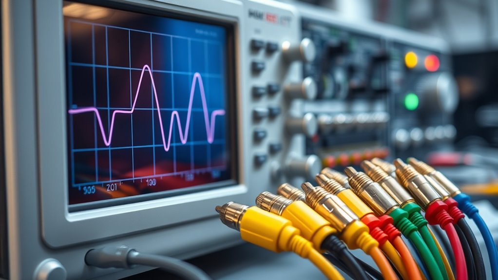
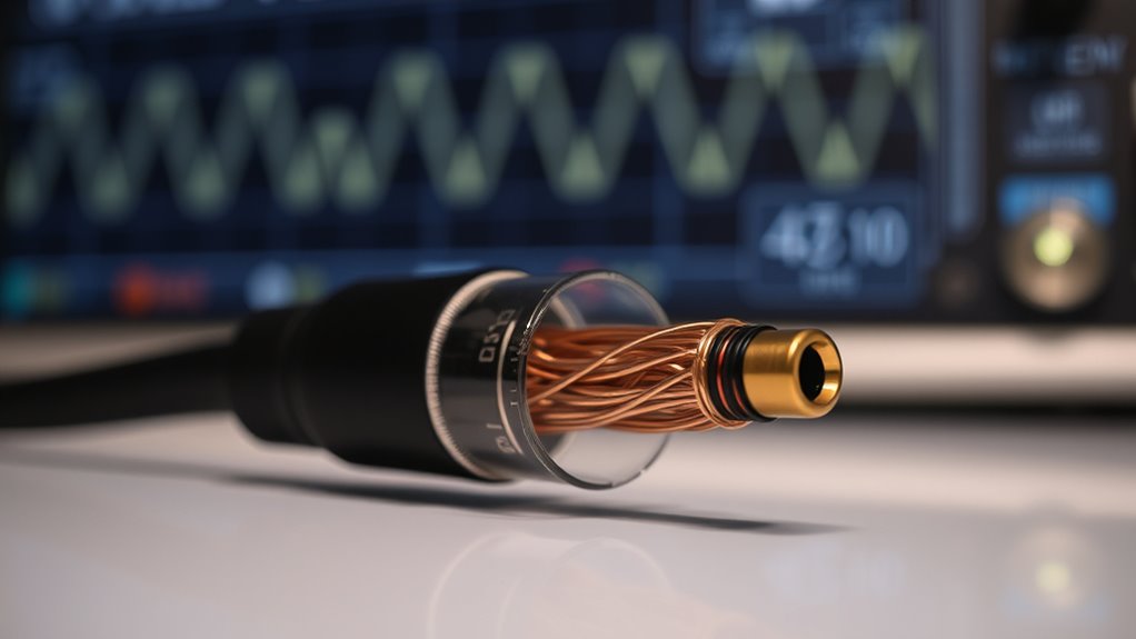
Cable capacitance and impedance are key factors affecting signal quality. Capacitance stores electrical energy between conductors, causing signals to weaken over longer distances and high frequencies. Impedance combines resistance, inductance, and capacitance that vary with frequency, influencing how signals flow. Understanding these properties helps you choose and troubleshoot cables for ideal performance in audio, data, or high-frequency systems. Keep exploring, and you’ll uncover how to manage these effects for better system reliability.
Key Takeaways
- Cable capacitance stores electrical energy between conductors, affecting signal attenuation and waveform integrity over long distances.
- Impedance combines resistance, inductance, and capacitance, influencing how signals propagate through cables at different frequencies.
- Capacitance decreases reactance as frequency increases, which can lead to higher signal loss at high frequencies.
- Proper cable selection, shielding, and length management help minimize parasitic capacitance and maintain signal quality.
- Measuring impedance and capacitance with specialized tools aids in troubleshooting and optimizing system performance.

CableDirect – 3ft RCA/Phono Cable, 2 × 2 Plugs, Stereo Audio Cable, Practically Break-Proof & Flawless Sound Quality (coaxial, subwoofer/amp/HiFi & Home Cinema/Blu-ray, Analog & Digital)
Unparalleled: Connect your analog or digital audio kit thanks to this RCA/phono cable’s 75 ohm impedance, making it…
As an affiliate, we earn on qualifying purchases.
As an affiliate, we earn on qualifying purchases.
What Is Cable Capacitance and How Does It Affect Signal Transmission
Cable capacitance refers to the ability of a cable to store electrical charge between its conductors, which can influence how signals travel through it. This capacitor behavior causes some of the electrical energy to be stored temporarily, affecting the timing and strength of the signal. As a result, high capacitance can lead to increased signal attenuation, especially over longer distances. When signals pass through a cable with significant capacitance, the stored charge can slow down the transmission, distorting the original waveform. This effect can weaken the signal’s clarity and reduce data accuracy. Understanding how cable capacitance impacts capacitor behavior helps you choose the right cables for your setup, ensuring minimal signal loss and ideal performance. Additionally, effective cable design can help mitigate the adverse effects of capacitance on signal integrity, and staying informed about industry standards ensures optimal compatibility and performance. The development of advanced materials in cable manufacturing further contributes to reducing unwanted capacitance effects, leading to more reliable signal transmission.

ALLOSUN – EM480B Audio Impedance Tester Digital LCD Insulation Resistance Megohmmeter Meter Tester with Bag
Power supplied by 6 pieces 1.5V battery, AA or equivalent.(Battery not provided by seller)
As an affiliate, we earn on qualifying purchases.
As an affiliate, we earn on qualifying purchases.
The Concept of Electrical Impedance in Cables
Electrical impedance in cables combines resistance, inductance, and capacitance, affecting how signals travel. You’ll notice that impedance varies with frequency, influencing signal quality and transmission efficiency. Understanding these components helps you optimize cable performance for different applications. A thorough understanding of impedance is essential for troubleshooting and designing effective cable systems, especially considering cable capacitance and its impact on high-frequency signals. Moreover, Kia Tuning modifications often require careful consideration of electrical parameters to ensure optimal performance and safety. Recognizing the effects of capacitance can also aid in minimizing signal loss and interference in complex systems.
Impedance Components Breakdown
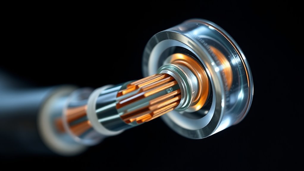
Have you ever wondered what makes up the total impedance in a cable? It’s a combination of resistive, inductive, and capacitive elements. The resistive part resists current flow, while inductive reactance opposes changes in current, especially at higher frequencies. Capacitive reactance, on the other hand, depends on the cable’s capacitance and the frequency, creating a reactive component that can either hinder or facilitate current flow. Together, these form the total impedance, which you need to consider for proper impedance matching. Proper matching minimizes reflections and signal loss, ensuring the best possible performance. Understanding how each component contributes helps you design cables that perform reliably across different environments and signal conditions. Recognizing the capacitance of cables is essential for optimizing audio and data transmission quality, especially in high-frequency applications. This breakdown clarifies the complex nature of impedance in cables, emphasizing the importance of vetted products for safety and effectiveness in various applications. Additionally, understanding electrical properties can help troubleshoot issues and improve overall system reliability. Moreover, considering skin effect can be crucial when dealing with high-frequency signals, as it impacts how current flows within conductors.
Frequency Dependence Effects
As impedance components combine to influence signal behavior, their effects become more pronounced at different frequencies. At higher frequencies, dielectric properties impact capacitance, causing the cable to behave more reactively. The skin effect also occurs, pushing current toward the conductor’s surface, increasing resistance and altering impedance. This frequency dependence means impedance isn’t static but varies with the signal’s frequency. To visualize this, consider the following:
| Frequency Range | Effect on Impedance |
|---|---|
| Low | Dominated by capacitance and dielectric properties, minimal skin effect |
| Medium | Increasing skin effect, resistance rises |
| High | Skin effect is significant, impedance shifts |
Understanding these effects helps optimize cable design and signal integrity across different frequencies, especially when considering cable capacitance and impedance in high-frequency applications. Recognizing how frequency-dependent behavior influences impedance can lead to more effective cable selection and system performance. Additionally, considering the dielectric materials used in cables can further improve impedance stability at various frequencies.
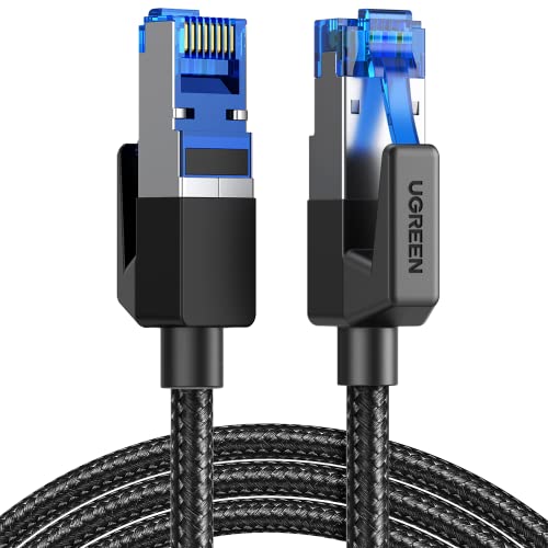
UGREEN Cat 8 Ethernet Cable 6FT, High Speed Braided 40Gbps 2000Mhz Network Cord Cat8 RJ45 Shielded Indoor Heavy Duty LAN Cables Compatible with Gaming PC PS5 PS4 PS3 Xbox Modem Router 6FT
40 Gbps 2000 Mhz High Speed: The Cat 8 ethernet cable support max. 40 Gbps data transfer and…
As an affiliate, we earn on qualifying purchases.
As an affiliate, we earn on qualifying purchases.
How Capacitance Influences High-Frequency Signals
Capacitance plays a crucial role in how high-frequency signals behave in a cable. As frequency increases, capacitive reactance decreases, allowing more current to pass through the capacitance. However, this also causes signal attenuation because the capacitor shunts part of the signal to ground, reducing the signal’s strength at the receiving end. The higher the capacitance, the lower the capacitive reactance, which amplifies this effect. This means that at high frequencies, the cable’s capacitance can considerably distort signals, leading to loss of detail or clarity. Understanding the impact of capacitance helps you select appropriate cables and design systems that minimize unwanted attenuation, ensuring your high-frequency signals remain strong and clear over the length of the cable. Additionally, considering noise levels of modern heat pumps can inform how electrical interference might impact signal integrity in certain environments.

TV Antenna for Long Distance Reception, Coverage Over 250 Miles, Signal Booster, HD Digital Amplification, 16.5 ft Coaxial HD Cable, Supports Local Channels 4K 1080p HD Indoor
This TV antenna supports 4K UHD and Full HD for crisp, detailed images. It receives popular channels like…
As an affiliate, we earn on qualifying purchases.
As an affiliate, we earn on qualifying purchases.
The Relationship Between Resistance, Inductance, and Impedance

Understanding how resistance, inductance, and impedance relate is essential for analyzing how signals travel through cables. Resistance opposes current flow, while inductance stores energy in a magnetic field, affecting how signals respond at different frequencies. Impedance combines both, influencing how signals encounter obstacles like cable shielding or wireless impedance mismatches. impedance shapes the overall signal path, blending resistance and inductance, which can be affected by the cable’s construction and environment. Visualize these interactions as:
Resistance, inductance, and impedance shape signal flow and quality in cables.
- Resistance acting like a narrow pipe resisting flow.
- Inductance creating a magnetic barrier that filters high frequencies.
- Impedance shaping the overall signal path, blending resistance and inductance.
- Cable shielding reducing external interference, impacting the cable’s impedance profile.
- The horsepower of electric dirt bikes impacts their performance, much like how impedance influences signal quality in cables. Additionally, understanding cable capacitance is crucial because it can cause signal attenuation or distortion at high frequencies.
Together, resistance and inductance determine the impedance, affecting signal integrity. Properly manage these factors ensures minimal signal loss and consistent performance across wired and wireless setups.
Practical Impacts of Cable Capacitance on Audio and Data Signals
When signals travel through cables, their quality depends heavily on how various electrical properties interact, especially capacitance. High capacitance can cause signal degradation by filtering out high-frequency components, which affects audio clarity and data integrity. In wireless transmission setups, excessive cable capacitance may introduce noise or reduce signal strength before reaching the receiver. For data signals, increased capacitance can lead to timing issues and errors, especially at higher speeds. Additionally, cable capacitance can make your system more vulnerable to signal interference, as it may act like an unintended antenna or filter. To guarantee peak performance, minimize capacitance through proper cable selection and routing, reducing the risk of distortion, interference, and loss of signal fidelity. Proper shielding and cable quality also play a vital role in managing cable capacitance for optimal signal transmission. Selecting cables with low capacitance ratings and ensuring proper installation practices can significantly improve overall system reliability and performance. Implementing appropriate cable management techniques further helps in reducing unwanted capacitance effects and maintaining signal integrity over longer distances. Incorporating advanced cable materials can also contribute to lowering capacitance and enhancing overall signal quality.
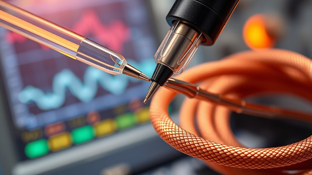
Measuring and Calculating Cable Capacitance and Impedance
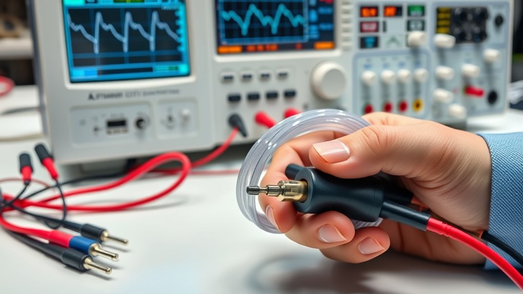
To accurately assess a cable’s electrical properties, you need to measure its capacitance and impedance using specialized tools and techniques. For fiber optics or wireless transmission, precise measurements guarantee signal integrity. Visualize this process:
- Use an LCR meter or network analyzer to connect to the cable ends, capturing real-time data.
- Apply a test signal and observe how the cable responds, noting phase shifts and attenuation.
- Calculate impedance by measuring voltage and current, then dividing to find resistance and reactance.
- For capacitance, analyze the stored charge relative to voltage changes.
These steps help you determine how well your cable performs, identify issues, and optimize designs, especially for high-speed fiber optics or wireless systems where even small capacitance variations impact performance.
Strategies for Minimizing Capacitance and Impedance in Cable Design

Reducing capacitance and impedance in cable design is essential for maintaining signal integrity and achieving high-performance transmission. One effective strategy is implementing shielding techniques, such as braided or foil shields, which minimize stray capacitance and prevent external interference. Keeping cable length short reduces parasitic capacitance, as longer cables naturally increase capacitance and impedance. Additionally, selecting appropriate cable geometries—like twisted pairs—helps balance impedance and reduce capacitance effects. Proper grounding techniques further diminish noise and interference, improving overall signal quality. By combining shielding methods with mindful cable length management, you can considerably lower capacitance and impedance, ensuring clearer signals and more reliable performance across your system.
Selecting the Right Cables Based on Capacitance and Impedance Requirements

Selecting the right cables requires carefully matching their capacitance and impedance specifications to your system’s needs. To do this, consider these key factors:
- Cable shielding – ensures interference reduction, especially in high-capacitance environments.
- Impedance matching – aligns with your equipment’s input/output requirements for ideal signal transfer.
- Connector compatibility – guarantees secure, reliable connections without signal degradation.
- Capacitance ratings – select cables with capacitance suited to your frequency range and signal integrity needs.
Troubleshooting Signal Issues Related to Cable Capacitance and Impedance

When you notice signal problems, start by checking for signs of signal degradation, such as noise or loss of clarity. Measure the cable’s capacitance to see if it’s causing unwanted effects, and make sure the impedance is correctly matched for your setup. Making proper adjustments can often restore ideal signal quality and prevent future issues.
Identifying Signal Degradation
Signal degradation often stems from issues related to cable capacitance and impedance mismatches, which can distort or weaken the transmitted signal. You might notice noise interference, where unwanted signals disrupt clarity, or signal attenuation, causing a weaker output. To identify degradation, visualize these signs:
- Sudden drop in audio or video quality
- Increased static or hissing sounds
- Intermittent or lost signal connections
- Delays or lag in data transfer
Measuring Capacitance Effect
To effectively troubleshoot issues caused by cable capacitance and impedance, measuring their effects is key. Start by inspecting cable shielding, which reduces external interference that can exacerbate capacitance effects, and ensure it’s properly grounded. Use a capacitance meter or LCR meter to measure the cable’s capacitance directly, focusing on the conductor insulation’s dielectric properties. Higher-than-expected capacitance values suggest signal degradation or timing issues. Keep in mind that poor conductor insulation can increase stray capacitance, affecting signal clarity. By comparing measurements to manufacturer specifications, you can identify problematic sections. This process helps pinpoint whether capacitance buildup or shielding deficiencies are causing signal attenuation or distortion, guiding your next troubleshooting steps effectively.
Adjusting Impedance Properly
Properly adjusting impedance is essential for minimizing signal reflections and ensuring ideal data transmission over cables. To do this effectively, focus on these key steps:
- Check the shielding effectiveness to prevent external interference from disrupting impedance balance.
- Inspect conductor insulation for damage or degradation that could affect impedance consistency.
- Use an impedance matching device, like a terminator, to align cable and equipment impedance levels.
- Ensure connectors are properly installed, maintaining solid contact without gaps or looseness.
Frequently Asked Questions
How Does Cable Material Affect Capacitance and Impedance?
You’ll find that cable material impacts capacitance and impedance because dielectric properties influence how much charge the cable can store, while conductor composition affects resistance and overall impedance. Materials with higher dielectric constants increase capacitance, and those with better conductor quality reduce resistance. By choosing materials with suitable dielectric properties and conductor composition, you can optimize cable performance for specific applications, ensuring minimal signal loss and better signal integrity.
Can Environmental Factors Change a Cable’s Capacitance or Impedance?
Environmental interference and temperature fluctuations can notably change a cable’s capacitance and impedance. When you experience electromagnetic interference or extreme temperatures, they can alter the dielectric properties and physical dimensions of your cable, leading to variations in capacitance and impedance. These changes can cause signal degradation or loss, so it’s essential to shield cables properly and avoid exposing them to harsh environmental conditions to maintain ideal performance.
What Are the Effects of Cable Length on Impedance and Capacitance?
Like a river widening, longer cables increase impedance and capacitance, affecting your signal. As cable length grows, you’ll notice more signal attenuation, which weakens your signal strength. It also impacts frequency response, making high-frequency signals harder to transmit accurately. Keep cables as short as possible to maintain ideal performance, ensuring your data remains clear and strong without distortion or loss.
How Do Connectors Influence Overall Cable Impedance?
Connector types substantially influence your cable’s overall impedance, especially if they’re mismatched with your equipment. Proper impedance matching ensures minimal signal loss and prevents reflections, which can degrade performance. Choose connectors designed for your specific impedance—like BNC or RCA—and ensure they’re compatible with your device. When connectors are well-matched, they maintain consistent impedance throughout your setup, providing clearer signals and better overall system reliability.
Are There Industry Standards for Acceptable Cable Capacitance and Impedance?
You’ll be pleased to know that industry standards exist to guide acceptable cable capacitance and impedance, making sure reliable performance. By adhering to standards compliance and employing thorough testing methodologies, manufacturers and users can confidently select cables that meet specific requirements. These standards help optimize signal quality and minimize interference, making your installations smoother and more dependable. Following them ensures your setup remains efficient and aligns with best practices across the industry.
Conclusion
By understanding cable capacitance and impedance, you can optimize signal clarity, reduce interference, and improve overall performance. You can select the right cables, measure accurately, and troubleshoot effectively. You can design smarter systems, minimize signal loss, and guarantee reliable transmission. Embrace these concepts, apply these strategies, and enjoy cleaner, stronger signals that meet your needs every time. With knowledge and care, you control your cables, your signals, and your success.